Monitoring groundwater is important
There are three reasons to monitor groundwater:
- to estimate the risk of rising watertables that could affect production
- to monitor the effect of management on watertables
- to monitor changes in water quality.
A single measure of depth to the watertable will not show if the watertable is rising, falling or static: a series of measurements taken regularly over at least five years enables the data to be used to:
- track direction of water level changes
- assess the risk of increasing saline land
- indicate the likely groundwater systems in a specified area
- identify when groundwater recharge occurs and the effect of seasonal conditions on groundwater levels
- evaluate the effect of land management practices on groundwater levels.
Which type of bore do you need?
There are two types of bores used for measuring groundwater levels:
- Observation wells: are suited to measure depth to the watertable in areas with unconfined aquifers. An observation well is slotted from the bottom of the bore to above the watertable and is not sealed above the slotted section except for a collar at the surface to prevent water flowing into the drilled hole (Figure 1).
- Piezometers: (Figure 1) measure the pressure (sometimes referred to as hydraulic head or piezometric head) of the groundwater over a specific portion of a confined or semi-confined aquifer. An observation well only measures depth to the watertable. Piezometers are slotted over only a short section below the watertable, within the aquifer. The borehole is sealed directly above the slotted section, usually with bentonite clay and this arrangement allows measurement of groundwater pressure at the slotted interval. Assess vertical groundwater gradients and flow directions using multiple piezometers at and across a site.
Locating monitoring bores
Locating monitoring bores depends on:
- the purpose (e.g. to determine salinity risk or impact of a particular land use)
- the hydrogeological complexity of the catchment.
To determine the risk of increasing salinisation, place bores away from groundwater discharge areas. Once groundwater nears the surface, it will usually stop rising and seasonal fluctuations are the main response.
Bores can be located either singly or aligned in transects on hillsides or groundwater flow paths. Start bore transects near the top of the hill and finish at or near the discharge site or valley floor. Ideally, place bores in a sequence of landscape positions such as the midslope, break of slope and the flats or valley floor (if salinity is not already present).
Placement and number of bores
Basic system
If the objective is to monitor the impact of revegetation, the most basic system to monitor the effectiveness of management is a shallow bore placed in the middle of the treatment area, matched with a shallow ‘control’ bore located in an adjacent, non-treatment area (at least 100m from the treatment) in a similar landscape position. Ideally, install bores before any treatment, to set the baseline depth to watertable and groundwater salinity.
This basic design compares groundwater level trends between treatments to detect their impact. Adding a deep piezometer at each site will provide important information about the depth to basement rock and define the underlying groundwater conditions that could be important in analysis of observed trends.
However, this approach will not define off-site impacts of the perennials, nor will it provide early warning of groundwater trends upslope (which may affect the treatment in the longer term).
Advanced system
A better monitoring system is a transect of bores, extending from the top of the sub-catchment, through the vegetated area, to the valley or saline area. Install shallow and deep bores:
- within the planted area/s
- in the valley or at the head of the discharge site
- in the mid-slope
- near the top of the catchment.
The number of sites and bores will depend on:
- the length of transect
- area and layout of perennials
- likely hydro-geologic complexity
- each major soil group
- changes in slope
- major landform sequences (e.g. upper slope, upland flat, midslope, lower slope and valley flat)
- areas of suspected change in underlying bedrock (e.g. bedrock highs, dolerite dykes or faults).
The requirements can be difficult to know without geophysical surveys. However, there are useful indicators, such as abrupt changes in slope, presence of rock outcrop or lineaments, or changes in coloration or shading on aerial photos.
Soils, slope, landform and underlying geology are often related, therefore a single bore site within the transect will can be affected by more than one of these factors.
An example of a monitoring transect is shown in Figure 2. Information obtained during drilling and initial monitoring has enabled the creation of the landscape section, which provides generalised, yet very valuable information about the hydrological processes occurring at the hill-slope or sub-catchment scale.
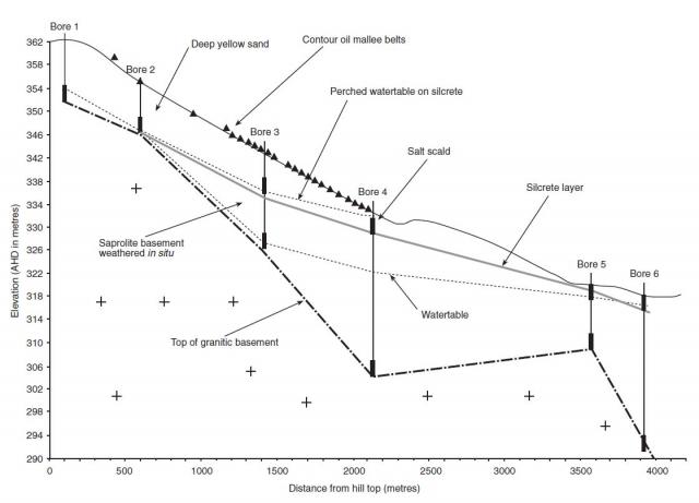
The complexity of the monitoring system chosen will depend on the resources available, the likely complexity of the groundwater system and the scale of the planting. For paddock scale revegetation within a small groundwater catchment, the basic system may be sufficient.
Use the more detailed monitoring system for large-scale revegetation systems covering several paddocks or properties. For example, broad scale perennial planting systems, such as oil mallee alleys that cover much of a groundwater sub-catchment, should use the transect approach, as results from a single bore will not be representative.
In all cases, a control bore or bores sited in an adjacent sub-catchment in a similar landscape position are required to verify that changes in groundwater levels are due to the treatment.
Depth of bores
For basic groundwater monitoring systems, install ‘shallow’ piezometers to about 3m below the watertable, with the bottom 2m of bore casing slotted . Backfill around the slotted section with washed gravel or coarse sand, put a bentonite plug on top and backfill the rest of the annulus with drill spoil.
During drilling, determine the depth of the watertable by observing when saturated drill spoil is returned. This can be more difficult for clayey textured soils, depending on the drilling method. However, the presence of moisture sheen on the soil surface when hand moulded usually means the sample is saturated and from below the watertable.
Shallow piezometers give approximate watertable depth while preventing root invasion and a good measure of the watertable salinity with which the tree roots will be interacting. Where very large areas of perennials are to be established and reductions in groundwater levels are likely to be large, install a second bore with the 2m screen 6m below the watertable.
To understand a site's hydro-geology, install a piezometer nest: a group of shallow and deep bores (to basement rock). Piezometer nests can define deeper groundwater systems, determine if there is a perched aquifer, help determine if it is a recharge or discharge site, and provide evidence of any impact of the deep groundwater system. Results from deeper piezometers are needed to construct a landscape cross section (Figure 1), and for modelling of the site during later evaluation.
Document the materials encountered during drilling, such as hardpan layers, sedimentary beds and fractured rock, as this will enable an accurate hydrological cross-section to be drawn. Knowledge of the layers will help interpret groundwater trends; for example, a hardpan layer may mean that the trees will only affect the groundwater above this point. Accurately survey bore positions and relative heights to enable drawing of cross-sections.
Installing monitoring bores
Drilling, casing and sealing bores
Drill observation wells and piezometers using rotary auger or rotary airblast rigs, and line the holes with 40 or 50mm diameter, class 9 or 12, PVC pipe. Slot the PVC pipe at its lower end, and use solid pipe above the watertable (see Figure 1).
Place an end cap with a hole in it on the bottom of the PVC casing to allow water to drain freely out of the pipe if the bore goes dry. This prevents false readings caused by trapped water. An end cap with bore identification information on the inside is fitted to the top of the monitoring bore to identify it and prevent rain or soil entering. Puncture the casing just below the cap, to allow pressure inside and outside the casing to equalise.
Pour washed gravel or coarse sand (about 1.6–3.2mm in diameter) down the outside of the pipe to fill the space between the soil and the slotted section. This allows water but not soil to flow into the bore.
Seal above the slotted section of a piezometer with a bentonite clay layer (Figure 1), to enable the pressure of the aquifer to be measured at a specific depth. Then fill the remaining space around the casing with soil or drill spoil, and a clay or cement seal set around the bore at ground level to prevent surface water from seeping down the outside of the casing.
‘Develop’ the bore by removing water by either pumping or airlifting. This will draw fine material from the aquifer through the gravel pack and screen and lift it out of the casing with the water. Airlifting or pumping will improve the hydraulic connection with the aquifer.
Airlifting pumps compressed air to the bottom of the casing to lift the water out. Pumping will achieve the same result, but if excessive fine material passes through the pump, the impellers may be damaged. Use a PVC elbow to direct the water down-wind and to control the discharge.
Identifying your bore
Bore identification codes usually consist of two to four letters and four numbers (e.g. 02RSI4S). The first two digits represent the year the bore was constructed. The next two letters represent the initials of the catchment, landholder or project. The following two digits represent the bore number and the last one or two letters represent the bore type, for example S for shallow piezometer or OB for observation well.
Protecting your bore
Protect the bore from livestock, fires and vehicles by placing a steel collar, drum or similar barrier over the above ground part of the casing, and mark the site using a painted steel fencepost or fibreglass pole. In cropped areas, make this protection very obvious!
Monitoring depth to water
There are two ways to measure the depth to water in a bore:
- tape measure and plopper
- electronic water level loggers.
Tape measure and plopper
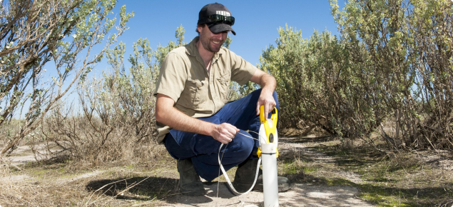
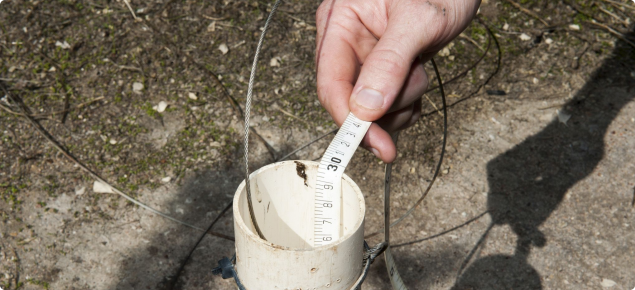
Measure water levels in the bores using a tape measure with an attachment that makes a noise or signal when it touches the water surface.
The simplest version is a ‘plopper’:
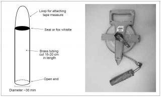
- made from a 15 to 20cm length of copper or stainless steel tube sealed at the top
- attached to a tape measure with a loop of wire or a key ring
- and a tape measure that is at least as long as the deepest groundwater level expected.
We recommend shortening the tape at the plopper end, by the the same length as the plopper: this avoids having to correct the readings to account for the length of the plopper. The end of the plopper that touches the water should be left open (see Figure 3).
Steps to measure the water level:
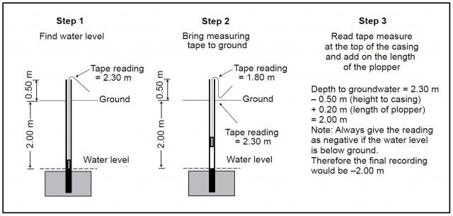
- Lower the plopper until it hits the water. The tape is then jiggled up and down until it makes a distinct ‘plopping’ sound when it contacts the water, hence its name (Step 1, Figure 3). To produce a more distinct sound, replace the seal at the top of the metal tube with a fox whistle, which is flat and circular.
- Bring the tape from the top of the casing to the ground once the water level has been found, then re-read the tape at the top of the casing – the new reading is then the depth below the ground surface (Step 2, Figure 4). Take care not to drag the tape over the hard edge of the bore casing to avoid wear to the tape and potential loss of the plopper tube down the bore.
- If the tape has not been adjusted to account for the extra length of the plopper, the final step is to add the length of the plopper attachment (Step 3, Figure 4).
Measurements with this technique give a reading accurate to within 1cm.
Record the water level in metres with the name of the bore and the date of measurement. If the water level is below ground, record it as negative (-), and positive (+) if it is above ground (which can happen in artesian bores).
Electronic water level loggers
Electronic water level loggers can record more frequent measurements, which enable more accurate assessment of groundwater level response to rainfall or pumping. A range of electronic water level loggers is available commercially through scientific equipment suppliers.
Monitoring water quality
The most common water quality factor is salinity. Salinity can be estimated from the electrical conductivity (EC) of water samples from the bore. EC can be measured in the field with a hand held meter; some meters will come with a second probe to measure pH. EC is usually measured in millisiemens per metre, however most meters will display the EC in the units that give the most precise measure of EC given its magnitude. It is best to record the EC units with the numerical value and do the unit conversion later as there is a large range of units with different conversion factors. Unit conversion factors are shown in Table 1. More information is in measuring soil salinity.
| Unit | Convert to millisiemens per metre (mS/m) |
|---|---|
| dS/m (decisiemans/metre) | x 100 |
| mS/cm (milliSiemens/centimetre) | x 100 |
| Mmhos/cm (millimohs/centimetre) | x 100 |
| µS/cm (microSiemens/centimetre) | x 0.1 |
| µmhos/cm (micromohs/centimetre) | x 0.1 |
Probes with long cables are available to measure EC without retrieving a sample from the bore. If using a probe on a long cable, ensure that the probe is lowered to at least the level of the top of the screened interval. You may wish to observe the EC at various depths below the watertable but the most representative value is the observation at the level of the screen. This may require the labelling of the cable with length markers if it is not already marked.
If a probe on a long cable is not available and a water sample has to be retrieved from the bore, use a pump or bailer. One advantage over physically retrieving a water sample is that several bore volumes of water can be removed before taking the sample to ensure that it is representative of the aquifer water rather than water that has sat stagnant in the bore casing. If using a pump, discharge the water into a bucket and place the probe in the bucket. Record the EC once the value has stabilised. A similar process can be adopted if bailing the bore but it is more time consuming.
Monitoring frequency
During the year
We recommend monitoring every month or two when bores are first contructed, then at regular quarterly or twice-yearly intervals. Aim to measure when the watertable is at its lowest (usually around March – late autumn – in the south-west of Western Australia) and at it highest (usually around September – late spring). The minimum we recommend is to measure once a year when the watertable is at its lowest.
The exception is bores on obviously salt-affected land: in these cases you may need to measure only every few years, unless you have radically changed management.
Over the years
Estimate trends in groundwater (static, rising or falling) by measuring over several years. Records over time will also show how the groundwater system responds to variations in the seasons (high, low and average rainfall years) or changes to land management practices.
Bores that are rising or falling rapidly should be monitored more often within and over years.
Trends in response to management and climate change may take 5 or more years to become obvious.
Recording the measurements
Use a recording sheet or electronic document for each bore, to record:
- bore name
- date
- depth to groundwater – if the bore is dry, we recommend you note the depth at which it is dry in case the casing is silting up or has been blocked by roots
- water quality measurements (usually salinity level and pH)
- site conditions (land use around the bore; recent weather or climate changes, inundation around the bore).
The data can be used to produce hydrographs, a graph depicting water levels over time, and analysed to show responses to the climate and management.
Maintenance
Clean any accumulated silt at the bottom of a bore by airlifting (the same procedure used to develop the bore when it is constructed). If there is insufficient water in the bore to lift the silt out of the bore, add water to the bore, airlift, then leave the bore several hours or days before measuring the water level – this allows the bore water to equilibrate with the aquifer. Always note when the bore is airlifted, as airlifting may affect the water quality readings.

